

Note
Go to the end to download the full example code.
FID and spin echo#

The simplest signal you can acquire is the free induction decay (FID): a pulse tips the magnetisation into the transverse plane and the receiver records what the precessing magnetisation emits. This Tour builds that sequence, checks the flip angle of its pulses with a Bloch simulation, and then adds a refocusing pulse and a pair of crusher gradients so that the acquisition is centred on a spin echo at the echo time you prescribe.
You will see how the flip angle sets the FID amplitude, how the echo time is timed from pulse centres rather than block edges, and how the crusher dephasing sets the shortest echo time.
Prerequisites: lesson 1 of the course.
The representation these objects belong to is described in Pulseq file format.
Free induction decay#
A free induction decay needs two things: an RF pulse and an acquisition
window. The scanner limits, the dead times and the rasters the events are
designed against are in the system object, as in
lesson 1.
The pulse is a block pulse, a rectangle of constant amplitude, 200 µs long.
You ask for a flip angle and pypulseqpp works out the amplitude. You make
four of them, at 10, 30, 60 and 90 degrees, to see how the signal follows the
flip angle. The delay starts each pulse after the RF dead time, and
use="excitation" tells an interpreter and the k-space analysis what the
pulse is for.
FLIP_ANGLES_DEG = (10.0, 30.0, 60.0, 90.0)

pulses = [
    pp.make_block_pulse(
        flip_angle=np.deg2rad(flip_angle),
        duration=200e-6,
        delay=system.rf_dead_time,
        system=system,
        use="excitation",
    )
    for flip_angle in FLIP_ANGLES_DEG
]
The ADC window records 8192 samples. The time between two samples is the
dwell time, and its inverse is the receiver bandwidth. You ask for a dwell
of 32 µs; calc_adc_timing() moves it onto the ADC raster and
makes the window end on the gradient raster.
dwell, acquisition = pp.calc_adc_timing(
    8192,
    32e-6,
    grad_raster_time=system.grad_raster_time,
    adc_raster_time=system.adc_raster_time,
)
adc = pp.make_adc(
    num_samples=8192, dwell=dwell, delay=system.adc_dead_time, system=system
)

print(
    f"dwell {dwell * 1e6:.0f} us, receiver bandwidth {1e-3 / dwell:.1f} kHz, "
    f"acquisition {acquisition * 1e3:.1f} ms"
)
dwell 40 us, receiver bandwidth 25.0 kHz, acquisition 327.7 ms
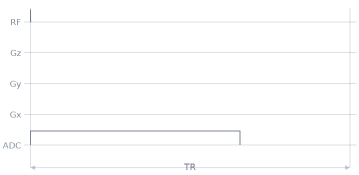
One repetition is two blocks: the pulse, then the acquisition. The 500 ms delay in the acquisition block is longer than the ADC window, so it sets the block duration and with it the repetition time.
seq = pp.Sequence(system=system)
for pulse in pulses:
    seq.add_block(pulse)
    seq.add_block(adc, pp.make_delay(500e-3))

ok, errors = seq.check_timing()
print(f"timing {ok}, {seq.num_blocks} blocks, {seq.duration()[0]:.2f} s")
timing True, 8 blocks, 2.00 s
The solid trace of the diagram is the first repetition; the shaded traces are the other three, which differ only in the pulse amplitude.
Flip angle#
sim_rf() runs a Bloch simulation of each pulse as it is
stored in the sequence. On resonance, a block pulse rotates the magnetisation
by its flip angle \(\alpha\), so the transverse magnetisation is
\(|M_{xy}| = \sin\alpha\):
on_resonance = []
for pulse in pulses:
    mxy, frequency = pp.sim_rf(pulse)[1:3]
    on_resonance.append(abs(mxy[np.argmin(abs(frequency))]))
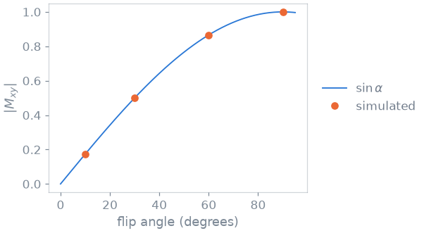
The four simulated pulses sit on the curve: the 90 degree pulse puts all the magnetisation in the transverse plane, and the others a fraction \(\sin\alpha\) of it.
Spin echo#
A FID starts decaying as soon as the pulse ends, and it decays faster than \(T_2\) because spins at different positions precess at slightly different frequencies. A 180 degree refocusing pulse at \(\mathrm{TE}/2\) reverses the phase each spin has accumulated, so the spins are in phase again at \(\mathrm{TE}\), and the ADC is centred there.
The refocusing pulse is rectangular like the excitation and has the same
duration, so twice the flip angle is twice the amplitude. The use tag
lets the k-space analysis invert the accumulated gradient integral at the
pulse centre, and lets an interpreter identify the pulse.
ECHO_TIME = 24e-3
VOXEL = 5e-3
CRUSHER_CYCLES = 4.0

excitation = pp.make_block_pulse(
    flip_angle=np.pi / 2,
    duration=200e-6,
    delay=system.rf_dead_time,
    system=system,
    use="excitation",
)
refocusing = pp.make_block_pulse(
    flip_angle=np.pi,
    duration=200e-6,
    delay=system.rf_dead_time,
    system=system,
    use="refocusing",
)

print(
    f"peak B1: excitation {abs(excitation.signal).max():.0f} Hz, "
    f"refocusing {abs(refocusing.signal).max():.0f} Hz"
)
peak B1: excitation 1250 Hz, refocusing 2500 Hz
Crusher gradients#
A refocusing pulse with a flip angle that is not exactly 180 degrees also
produces a FID, which would overlap the echo. Two crusher gradients of equal
area and equal polarity, one before and one after the refocusing pulse, remove
it. The pulse inverts the phase accumulated in the refocused pathway, so the
second crusher unwinds what the first wound. A pathway that crosses the pulse
without being inverted, such as that FID, sees the two areas add, and is left
wound through CRUSHER_CYCLES cycles across a voxel, which integrates to
nothing over it.
So you prescribe a crusher by the phase it winds across a voxel: an area
\(A\) turns the magnetisation through \(A\,\Delta x\) cycles across an
extent \(\Delta x\). make_crusher() takes the dephasing
and the voxel and solves the shortest gradient that delivers it within the
amplitude and slew limits.
crusher = pp.make_crusher(CRUSHER_CYCLES, VOXEL, channel="z", system=system)[0]

print(
    f"crusher: {1e3 * pp.calc_duration(crusher):.2f} ms for "
    f"{CRUSHER_CYCLES:.0f} cycles across {1e3 * VOXEL:.0f} mm"
)
crusher: 0.86 ms for 4 cycles across 5 mm
Echo timing#
The echo time is measured between pulse centres, not block edges. A block
longer than the events in it is a delay, and the two delays below absorb
whatever the pulses, their dead and ringdown times and the crushers do not
occupy: the refocusing pulse centre goes at \(\mathrm{TE}/2\) and the
acquisition centre at \(\mathrm{TE}\). You put each delay on the
block-duration raster with round_to_raster(); a duration off
the raster is rounded up when the block is added, which moves the echo by up
to one raster period. The rasters are described in
Pulseq file format.
SAMPLES = 512

dwell, acquisition = pp.calc_adc_timing(
    SAMPLES,
    20e-6,
    grad_raster_time=system.grad_raster_time,
    adc_raster_time=system.adc_raster_time,
)
adc = pp.make_adc(
    num_samples=SAMPLES, dwell=dwell, delay=system.adc_dead_time, system=system
)

print(
    f"dwell {dwell * 1e6:.0f} us, acquisition {acquisition * 1e3:.2f} ms, "
    f"half of it {acquisition * 5e2:.2f} ms"
)


def centre(pulse):
    """Time from the start of a block to the centre of the pulse in it."""
    return pulse.delay + pulse.shape_dur / 2


def delays(echo_time, crusher_event):
    """The two delay blocks, on either side of the refocusing pulse."""
    crusher_duration = pp.calc_duration(crusher_event)
    before = (
        pp.calc_duration(excitation)
        - centre(excitation)
        + crusher_duration
        + centre(refocusing)
    )
    # The acquisition is centred on the echo, so what has to fit after the
    # refocusing pulse is the dead time and half the acquisition window.
    after = (
        pp.calc_duration(refocusing)
        - centre(refocusing)
        + crusher_duration
        + system.adc_dead_time
        + acquisition / 2
    )
    raster = system.block_duration_raster
    return (
        pp.round_to_raster(echo_time / 2 - before, raster),
        pp.round_to_raster(echo_time / 2 - after, raster),
    )


def spin_echo(echo_time, crusher_event):
    """One repetition of the spin echo, at the given echo time."""
    first, second = delays(echo_time, crusher_event)
    seq = pp.Sequence(system=system)
    seq.add_block(excitation)
    seq.add_block(pp.make_delay(first))
    seq.add_block(crusher_event)
    seq.add_block(refocusing)
    seq.add_block(crusher_event)
    seq.add_block(pp.make_delay(second))
    seq.add_block(adc)
    return seq


seq = spin_echo(ECHO_TIME, crusher)

ok, errors = seq.check_timing()
print(f"timing {ok}, {seq.num_blocks} blocks, {1e3 * seq.duration()[0]:.2f} ms")
dwell 20 us, acquisition 10.24 ms, half of it 5.12 ms
timing True, 7 blocks, 29.34 ms
To check the timing, read the pulse centres back from the k-space analysis: the refocusing pulse should be at half the echo time after the excitation, and the midpoint of the acquisition window at the echo time. The analysis returns the time of each ADC sample, so the midpoint of the window is the mean of the first and the last of them.
_, _, t_excitation, t_refocusing, t_adc = seq.calculate_kspace()
window_centre = (t_adc[0] + t_adc[-1]) / 2

print(
    f"prescribed TE/2 {1e3 * ECHO_TIME / 2:.3f} ms, "
    f"refocusing centre {1e3 * (t_refocusing[0] - t_excitation[0]):.3f} ms\n"
    f"prescribed TE   {1e3 * ECHO_TIME:.3f} ms, "
    f"acquisition midpoint {1e3 * (window_centre - t_excitation[0]):.3f} ms"
)
prescribed TE/2 12.000 ms, refocusing centre 12.000 ms
prescribed TE   24.000 ms, acquisition midpoint 24.010 ms
The refocusing pulse lands on the prescription and the acquisition midpoint lands half a block-raster period from it. Rounding a delay to the raster moves what follows it by at most half a period, so the echo time is realizable only to that resolution.
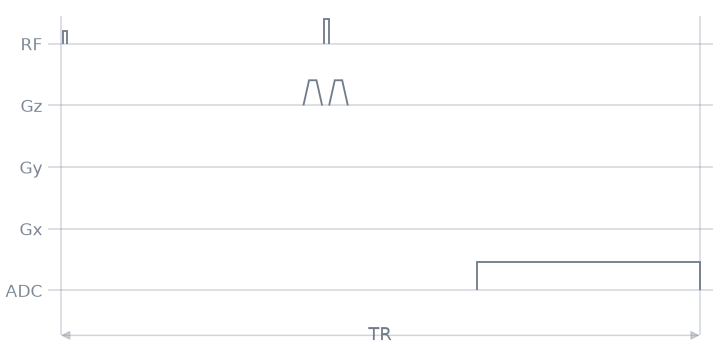
The sequence diagram shows the crushers on the slice axis, which carries no other gradient in this non-selective experiment:
Minimum echo time#
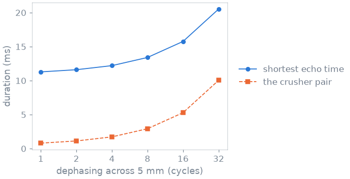
Both delays shrink as the echo time is shortened, and the first of them to reach zero sets the shortest echo time. The crusher pair is the term in that budget you control: more dephasing is a longer gradient at the same amplitude limit, on both sides of the refocusing pulse. You find the shortest echo time for each dephasing, and check that the sequence built at that echo time passes the timing check.
CYCLES = (1.0, 2.0, 4.0, 8.0, 16.0, 32.0)


def shortest_echo_time(crusher_event):
    """The smallest echo time at which neither delay block is negative."""
    raster = system.block_duration_raster
    before, after = (-delay for delay in delays(0.0, crusher_event))
    return raster * np.ceil(2 * max(before, after) / raster)


shortest = []
for cycles in CYCLES:
    event = pp.make_crusher(cycles, VOXEL, channel="z", system=system)[0]
    echo_time = shortest_echo_time(event)
    ok, _ = spin_echo(echo_time, event).check_timing()
    shortest.append(
        {
            "cycles": cycles,
            "crusher": pp.calc_duration(event),
            "echo_time": echo_time,
            "timing": ok,
        }
    )
cycles      crusher    shortest TE   timing
     1      0.40 ms       11.28 ms     True
     2      0.56 ms       11.60 ms     True
     4      0.86 ms       12.20 ms     True
     8      1.46 ms       13.40 ms     True
    16      2.64 ms       15.76 ms     True
    32      5.02 ms       20.52 ms     True
Half of the acquisition window sits between the refocusing pulse and the echo, so the shortest echo time is bounded below by the acquisition duration whatever the crushers do, and the crusher pair is added to that floor. The duration of the pair grows as the square root of the dephasing while it is slew-limited and in proportion to it once the amplitude limit is reached, so the last doublings add the most to the echo time.
Specification#
What this Tour built, stated the way you would ask an agent for it:
Write a pypulseqpp pulse-acquire sequence for a scanner with
32 mT/m and 130 T/m/s, 100 us RF dead time, 20 us ringdown and
10 us ADC dead time. Play four 200 us block pulses at 10, 30, 60
and 90 degrees, each followed by an 8192-sample ADC at 32 us dwell,
with a TR of 500 ms, and verify the flip angles with sim_rf against
sin(alpha). Then write a spin echo: a 90 degree excitation and a
180 degree refocusing block pulse of 200 us, a z crusher of 4
cycles across 5 mm on either side of the refocusing pulse, and a
512-sample ADC at about 20 us dwell centred on TE = 24 ms. Put the
two delays on the block raster, check the timing, read the pulse
centres back with calculate_kspace, and find the shortest TE for
1 to 32 crusher cycles.
Total running time of the script: (0 minutes 0.360 seconds)